angrybacon
New member
- Joined
- Jan 10, 2016
- Messages
- 1
- Reaction score
- 0
- Points
- 0
Hey all - I'm installing a remote start/keyless entry on my brother's '03 Alero, and I'm having difficulty with getting the keyless entry to work. I got the remote start working with a Passlock II bypass module, but the goofy "one wire negative pulse" lock system has me baffled.
I've searched high and low for answers, even checking online resources like Bulldog's help desk and the12volt forum articles, and I'm coming up short.
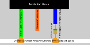
I can't seem to find any useful information as far as how to make this work. I'm installing a Crimestopper RS7-G5 two-way remote start with keyless entry. I've got all essential wires hooked up correctly, including brake pedal input, tach input, and starter/accessory wires. The only part that's stumping me is the final two wires for the remote start - a green wire for "negative pulse out - lock" and a blue wire for "negative pulse out - unlock".
From what I understand, there's a white wire in the harness behind the driver's kick panel that controls the locks. If I cut this wire, the locks stop working, and if I re-attach the wires, the locks work. The wire has a constant +12v going to it, and if I press the lock button on the door, the voltage drops to 0. Seems pretty simple, this circuit is operated by a ground-side switch.
However, when I hook up the green and blue wires the way the manual says, nothing happens. Also, if I hit the lock button on the door while the lock wires are connected, the remote starter kicks in and starts the engine. Something is obviously not right, I have a feeling that I may need to install some diodes, but I tried 12v zener diodes on both wires and it didn't help. Somewhere online I read about using 12v 4n1001 diodes... Are these different than zener diodes?
Any help would be greatly appreciated. I can't find any information from Crimestopper's website on application-specific stuff, the best I could find were from the following links:
http://www.the12volt.com/installbay/forum_posts.asp?tid=21067
http://www.bulldogsecurity.com/bdnew/vehiclewiringdiagrams.aspx
http://alarmsellout.com/support/diagrams/vehicle/OLDSMOBILE ALERO 1999-2003.pdf
http://diagrams.marktoonen.nl/DOWNLOADS/17044_ALERO_ALERO 1 WIRE JBS UNITS.pdf
The last link provided is the most pertinent one for me - should I be using relays for the installation as pictured in the first option? Is there something I'm doing wrong? Perhaps I should be using the gray wire at the BCM harness instead of the white wire behind the driver's kick panel?
Any assistance is greatly appreciated, I'm totally stumped and can't seem to figure this one out.
P.S. attached is a crudely-drawn diagram of how my wires are currently hooked up and not working.
I've searched high and low for answers, even checking online resources like Bulldog's help desk and the12volt forum articles, and I'm coming up short.
I can't seem to find any useful information as far as how to make this work. I'm installing a Crimestopper RS7-G5 two-way remote start with keyless entry. I've got all essential wires hooked up correctly, including brake pedal input, tach input, and starter/accessory wires. The only part that's stumping me is the final two wires for the remote start - a green wire for "negative pulse out - lock" and a blue wire for "negative pulse out - unlock".
From what I understand, there's a white wire in the harness behind the driver's kick panel that controls the locks. If I cut this wire, the locks stop working, and if I re-attach the wires, the locks work. The wire has a constant +12v going to it, and if I press the lock button on the door, the voltage drops to 0. Seems pretty simple, this circuit is operated by a ground-side switch.
However, when I hook up the green and blue wires the way the manual says, nothing happens. Also, if I hit the lock button on the door while the lock wires are connected, the remote starter kicks in and starts the engine. Something is obviously not right, I have a feeling that I may need to install some diodes, but I tried 12v zener diodes on both wires and it didn't help. Somewhere online I read about using 12v 4n1001 diodes... Are these different than zener diodes?
Any help would be greatly appreciated. I can't find any information from Crimestopper's website on application-specific stuff, the best I could find were from the following links:
http://www.the12volt.com/installbay/forum_posts.asp?tid=21067
http://www.bulldogsecurity.com/bdnew/vehiclewiringdiagrams.aspx
http://alarmsellout.com/support/diagrams/vehicle/OLDSMOBILE ALERO 1999-2003.pdf
http://diagrams.marktoonen.nl/DOWNLOADS/17044_ALERO_ALERO 1 WIRE JBS UNITS.pdf
The last link provided is the most pertinent one for me - should I be using relays for the installation as pictured in the first option? Is there something I'm doing wrong? Perhaps I should be using the gray wire at the BCM harness instead of the white wire behind the driver's kick panel?
Any assistance is greatly appreciated, I'm totally stumped and can't seem to figure this one out.
P.S. attached is a crudely-drawn diagram of how my wires are currently hooked up and not working.